-
Most Popular
Learning to make sprites
I was looking through the contents of the cassette that came with the ... Read More!Amstrad 3.5" Floppy drive - DSK to Disc
So you've got the floppy drive all powered and plugged in, but got no Amstrad CPC software on 3.5" d... Read More!Connecting a 3.5" floppy drive to an Amstrad 464 without modifying the drive or DDI-1
Quite some time ago I bought a DDI-1 interface to use with my amstrad 464's. Just the interface with... Read More!Yet more Amstrads added to the collection - ALT-386sx and PCW8256
If you haven't guessed already, I like my Amstrad computers. Purely because of nostalgia and curiosi... Read More!Schneider (Amstrad) CPC 664 surprise
As a collector of Amstrad machines, the holy grail to me is the Amstrad CPC 664. Only manufactured f... Read More!
Amstrad 3.5" Floppy drive - Making a new ribbon cable, case and switchesCreated on: 07-07-2019 By Gee |
|
So if you've followed the previous blog posts about making a PC 3.5" floppy drive work with your Amstrad CPC 6128, then you should have a working drive and be able to make physical copies of the disc images you have.
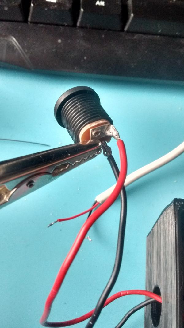
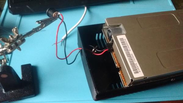
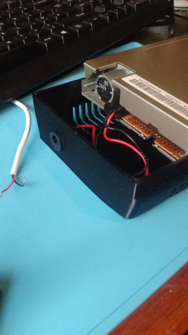
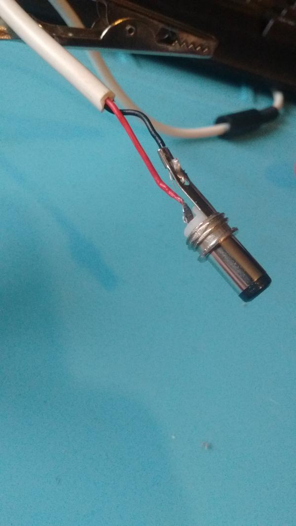
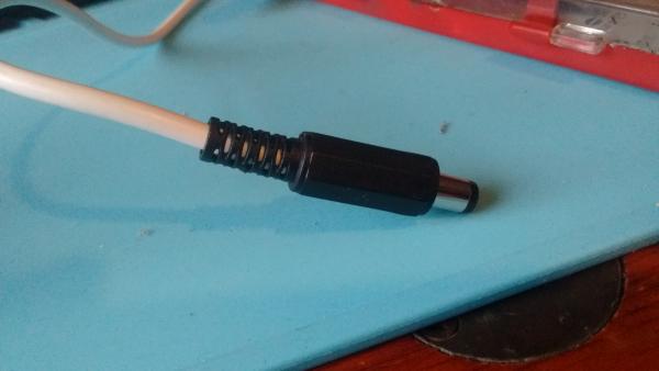
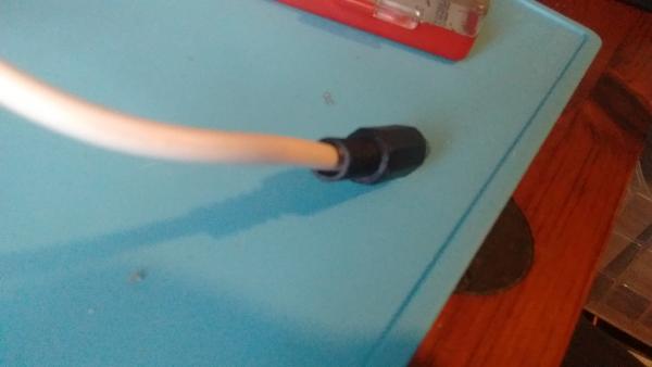
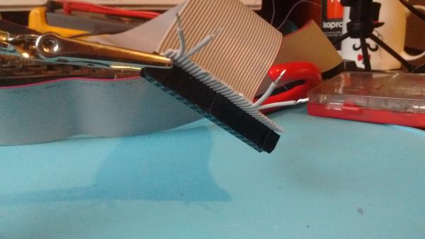
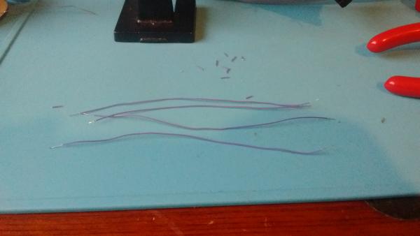
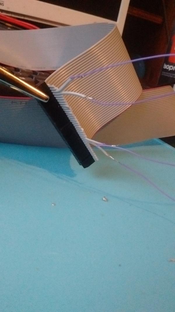
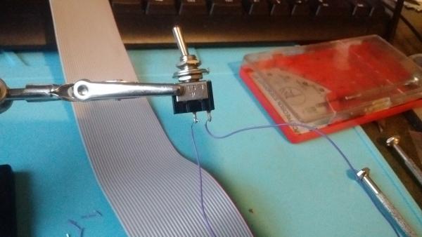
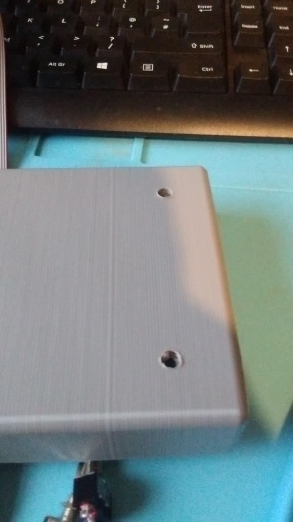
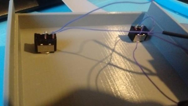
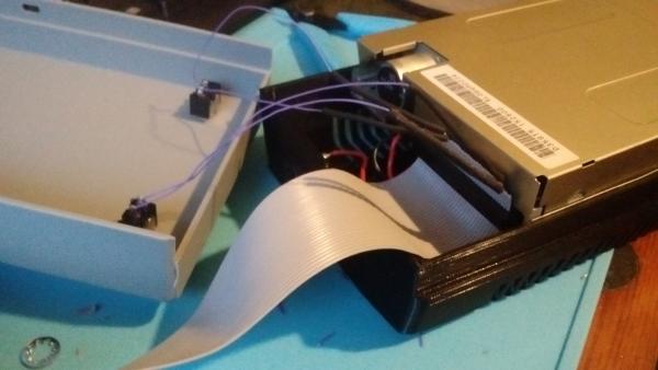
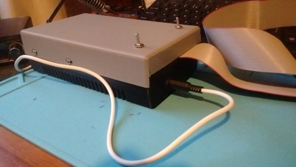
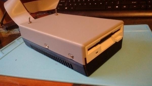
To make things better I decided to make my own ribbon cable, connect some switches so I can choose side A or B on the disk AND also a switch to make the external drive take over as drive A. Sadly doing this method doesn't change the internal drive to drive B. It is possible, but I don't fancy doing it as it involves cutting traces on the board. Not something I want to do to my 30+ year old machine. It's made it this far, no point in killing it now. To make the ribbon cable, I bought half a metre of 34 way ribbon cable, a 34 way edge connector and then a 34 way floppy IDE header style connector. Once I had them I set about making my new cable. I thought this was going to be fairly simple. Ensure I line up all the pins correctly and then use the backing of the connector to force the ribbon onto the pins that in turn cut into the ribbon and then make contact with the wires. Simple right? Yeah, I tried this method and broke both of my new connectors. One of them was £3 because they're a little rare now. That and I bought an individual one instead of a pack. Something I regretted after braking the only one I bought. So to get the connectors on properly I used a pair of needle nose pliers and pushed the ribbon either side of the pins. This worked great for the edge connector as the pins were far enough apart that I could fit the pliers in. To do the Floppy IDE connector I used two jewelers screwdrivers and took my time to do the same thing. Once the connections were on, I trimmed down the excess ribbon leaving wires pairs 31,32 and 11,12. These I extended using some random wire that I soldered on. I then soldered the opposite ends onto some switches. This gives me both the ability to use side 1 and 2 of the floppy disk (telling the drive to read from one read/write head instead of the other) and makes me able to use my external drive as drive A. I previously drew up the case I wanted on CAD and 3d printed it out. I didn't design in any holes for the switches so I just used a 5.5mm drill to make a couple. Once the switches were in and secured properly the drive was usable in all the ways I wanted it to be, easily. I made some changes to the way the drive is powered. I kept the same cable but instead of having a soldered connection between the USB cable and the berg connector, I placed in some proper DC power connections. The result was pretty good, except the male plug on the USB cable is a little thinner than the cable relief on the connection. Doesn't matter too much as it's just for home use. If I was making these to sell, it'd be something I'd like to rectify somehow. So that's my 3.5" external drive complete! I might make another one to make a video of me doing all this for others to watch rather than reading all my blog. Viewing is easier than reading haha! |
|
|