-
Most Popular
Learning to make sprites
I was looking through the contents of the cassette that came with the ... Read More!Amstrad 3.5" Floppy drive - DSK to Disc
So you've got the floppy drive all powered and plugged in, but got no Amstrad CPC software on 3.5" d... Read More!Connecting a 3.5" floppy drive to an Amstrad 464 without modifying the drive or DDI-1
Quite some time ago I bought a DDI-1 interface to use with my amstrad 464's. Just the interface with... Read More!Yet more Amstrads added to the collection - ALT-386sx and PCW8256
If you haven't guessed already, I like my Amstrad computers. Purely because of nostalgia and curiosi... Read More!Schneider (Amstrad) CPC 664 surprise
As a collector of Amstrad machines, the holy grail to me is the Amstrad CPC 664. Only manufactured f... Read More!
Amstrad 3.5" Floppy drive Getting the Ready signalCreated on: 16-06-2019 By Gee |
|
Hey again folks.
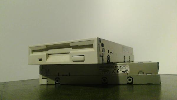
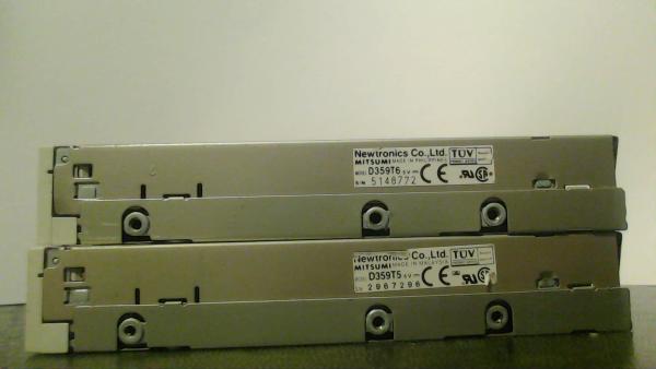
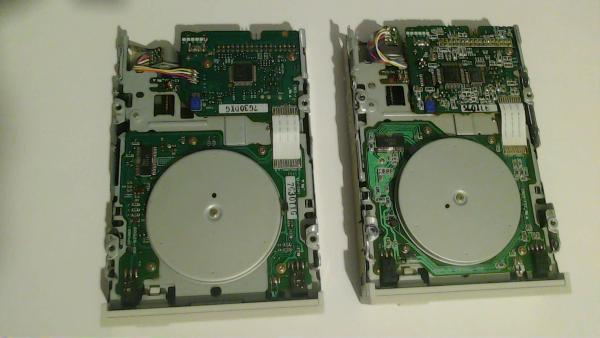
I now have a working 3.5" floppy drive that I have loaded software onto using my pc, then it has read fine on the Amstrad. This has opened up a whole plethora of software for me to be able to use on my Amstrads, and what do I go and use on it? An address book! I've been meaning to note down all my families addresses for an age, so this gave me an excuse to use my Amstrad for something constructive. So! how is it done? Well, it's quite simple actually. I read over an article on how to set the ready signal on a specific drive. After which I found, and bought two of them on eBay. The ones I bought were Mitsumi newtronics d359t5 and d359t6. Once they arrived, I checked the circuit board on them both to see what the differences were between the two. It turned out that the t6 has much smaller surface mounted components than the t5. Both have surface mount components, but the t5 has slightly larger components. The reason that I was looking at this was due to the article that I had read. In that, I had read about these drives having a resistor that you can de-solder and then re-solder onto a 'rdy' set of solder pads. This is important and the Amstrad requires the drive to produce a ready signal to work. PC's do not. Seeing as these are PC floppy drives, we need to do this modification to the one being used by the Amstrad. There is another way to produce a ready signal but this way means that we don't need to have a random wire poking about on our ribbon cable. So I set about removing and re-soldering on the resistor in question. The problem that I had was that I don't have a hot air station to be able to work on surface mount components very easily. All I have is my trusty soldering station and I thought that would be good enough. After using my solder sucker to remove as much solder from the resistor and it's pads, I used a set of tweezers to grab said resistor and pull gently as I placed the soldering iron on one pad then the next, over and over. This worked, but I pulled slightly too much at one point and took a solder pad with the resistor when it finally came free. This wasn't a problem as I wasn't going to be turning the drive back into a PC floppy drive. Once I cleaned the ripped off solder pad from the resistor, I set about putting it onto the rdy pads. It went on easily enough, but rather squint. I straightened it up just to help my OCD from going into meltdown. That was all that was needed to modify this floppy drive! The next step was to get the drive powered and connected to the Amstrad external floppy drive expansion port. |
|
|