-
Most Popular
Learning to make sprites
I was looking through the contents of the cassette that came with the ... Read More!Amstrad 3.5" Floppy drive - DSK to Disc
So you've got the floppy drive all powered and plugged in, but got no Amstrad CPC software on 3.5" d... Read More!Connecting a 3.5" floppy drive to an Amstrad 464 without modifying the drive or DDI-1
Quite some time ago I bought a DDI-1 interface to use with my amstrad 464's. Just the interface with... Read More!Yet more Amstrads added to the collection - ALT-386sx and PCW8256
If you haven't guessed already, I like my Amstrad computers. Purely because of nostalgia and curiosi... Read More!Schneider (Amstrad) CPC 664 surprise
As a collector of Amstrad machines, the holy grail to me is the Amstrad CPC 664. Only manufactured f... Read More!
Trying to fix my old PC case and making it worse...Created on: 21-03-2019 By Gee |
|
I've had my PC case for a rather long time now. In fact I think it's about 8 or 9 years old now.
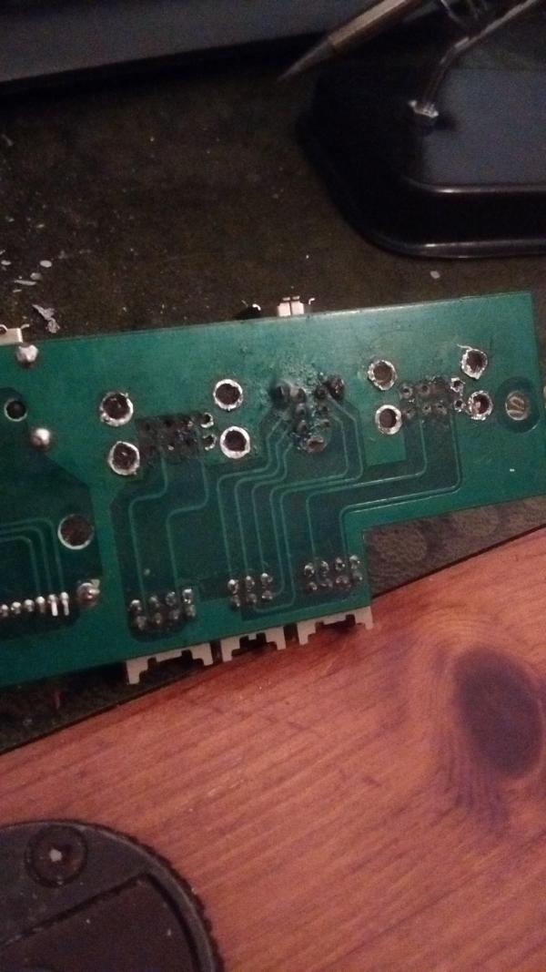
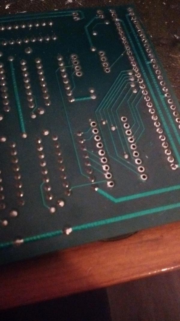
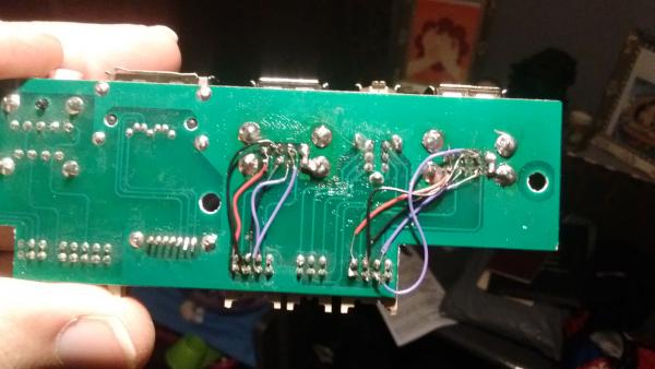
It's a pretty good case that I bought when I was really into my PC gaming, lots of air flow and water cooling ready. Not that I have ever used water cooling in my computers. Due to lots of wear and tear of the front USB ports, they eventually disintegrated. This happened a long time ago and I even considered buying a new case to replace that one simply due to these USB ports being broken and looking hideous. However, I believe that you should always try to repair something before replacing it. Replace it only if it's not doing what its supposed to and irreparable. Anyway, less of my beliefs and more about what went on with this. The USB ports (both front double ports broke) required replacing and I first had to find out if they were fairly standard through hole mounted on a PCB. So I set about tearing the whole case to pieces one day and cleaned out all the fans and grills whilst I was at it. The only clean like that it's ever had. There was so much dirt in there that I forgot that almost all the fans lit up with LED's. I eventually worked out how to get the top of the case off and get access to the PCB. I got that off by removing three screws and then using a knife to remove all the hot glue that held all the cables in place in the ports. The ports were indeed through hole mounted which made the idea of replacing them all the more appealing. I put the rest of the case back together and then set about trying to de-solder the ports from the PCB. I managed to get SOME of the solder to flow, but using just solder wick proved almost pointless. It took forever and I didn't seem to get anywhere very quick. I ordered my replacement ports and also a solder sucker and left the PC case with power switch wires, and other such wires that were in the same part of the case as the front USB ports, hanging out and just looking a mess. Eventually the solder sucker arrived and also my new USB ports. This is where the fun really began. I'm a complete novice at this stuff, thats the whole point in me making this blog really. So that others can learn from my mistakes and I can also remember it down the line. So let me tell you all the things I done wrong and then how I fixed it. The first thing that I done wrong was to have the heat too high on my soldering iron. I was turning it up to 380c to get the large pins that are connected to the ground plane on the board, to melt. I managed to get the solder mostly free from those with my new £2 solder sucker and i then set about removing the solder from the much smaller pins that actually make the USB port work. I din't turn the heat down.. I did use flux whilst I was doing this in the hope that it would help, but i'm not sure if it did. I managed to get a couple of the pins solder free, or so I thought. But some of them I just couldn't get the solder to flow properly and use the solder sucker at the same time, in the right space to have the suction actually pull the solder out. This ended up with me having the iron on the pins for far too long and I managed to pull out almost all of the pads from the pcb. I wasn't too deterred by this as I knew I could just run some wire to correct it. It was rather annoying that I had done it though. I later used a different soldering iron tip that was quite a bit smaller at the end and practiced on an old destroyed Amiga 500 memory expansion board. So if I destroyed anything on that, there wasn't anything lost. I should have done that first! Practice makes perfect eh? I did notice that the tip that I was using wasn't melting the solder with the very tip, but a bit further up. That made things a bit more difficult when trying to get solder to flow in confined spaces. But thats a post for another day (when/if I finally get one of the Amiga 500's fixed). After I got the old USB ports off of the board, I set about trying to put the new ones on. There was a tiny bit of solder still in some of the holes, so I thought i'd just use the iron to flow that as I push the new USB port into position. This was clearly not the best way to do things as I had to try flow one pin, then another, then back and forth for a bit. The whole time, heating the whole board up more and more. I changed my mind with this tactic and thought I'd just use a very small drill bit in my 'Dremil' like tool to open the holes up. But to get access to them, i'd need to remove the new port that I had managed to get part of the way in already. This ended up breaking a pin and the pin was stuck in the board. Removing this also removed part of the trace it was attached to. So I was definitely running wires now! After I decided on a plan of action (another thing I should have done first), I drilled out those tiny holes where the solder was refusing to come out of, put the new USB ports in and then soldered the larger feet in first. I then set about cutting different coloured wire to solder the correct pins to each other on the board. To save wire and time,I just connected the ground pins together and then to one of the USB ports feet, which itself was connected to ground. I also Wired up the 5V lines together (one line to each double port). The rest of the wires just look a mess. I put the cables back into the PCB and tested it out. I had 75% success result on first test as only one of the ports wasn't working. I then noticed that my solder joint wasn't actually a join on one of the wires to that port. So after fixing that, I put it all back together and they now all work! and the best bet is that my PC case is complete again. No need to buy that new PC case. |
|
|